Design
A single sample study, finite element analysis.
Time and setting
The study was accomplished in the Nanfang Hospital of Southern Medical University from June 2012 to February 2013.
Subjects
A healthy volunteer (male, 26 years old, and 70 kg in weight) was selected without foot and ankle injuries or disease by X-ray examination.
Inclusion criteria: (1) healthy volunteer; (2) the participant with informed consent of the test process; (3) the whole test met principles of medical ethics.
Exclusion criteria: (1) patients with foot or ankle injuries; (2) the X-ray performing ankle tumors, deformities or other diseases.
Methods
Geometry of finite element models
Bilateral ankles of the participant were scanned by a spiral CT (16-slice MSCT, GE, USA) with the tube voltage of 120 kV and the electric current of 65-150 mA. The exposure time was 0.5 to 1 second. The bone window and the slice thickness of 0.625 mm were selected. The sweep was from 20 cm above the ankle to the plantar plane. The data were saved in DICOM format including 289 pictures. The right ankle’s two-dimensional DICOM format data were imported into Mimics 13.0 as a sample, and the image segmentation was done with the appropriate gray threshold setting and the STL format output. Then, the STL format file was imported into Geomagic 10.0 for smooth, and the normal geometric model (Figure 1) was generated. Based on the normal model, wedge osteotomies were done by reducing calcaneal height for 5, 10, 15, and 20 mm, respectively, to generate pathological models. Four models (Figure 2) were generated and exported in IGES format file after fitting surface. All models adopted solid 185 unit, the node number and the unit number are shown in Table 1. A total of five finite element models including the normal model were imported into the finite element analysis software, Ansys 13.0, for post-processing analysis.
.jpg)
.jpg)
Material propertiesIn this study, internal fixation materials and bone materials are homogeneous and isotropic[4-12], and the material properties are referred in the relevant references[13-19] (Table 2).
Boundary conditions and loads
Supposing the fracture plate was broken completely, in contact, it still has the friction coefficient of 0.2[5]. As the boundary condition, the finite element models were fixed in all nodes in the lower margin of the calcaneus and foot weight-bearing area, which means the displacements on the X, Y, and Z axes of each distal node is 0. The effect of ligaments was ignored to simplify the model. At last, a 700 N axial force was applied on the tibial side of the model to calculate the stress distribution.
Evaluations
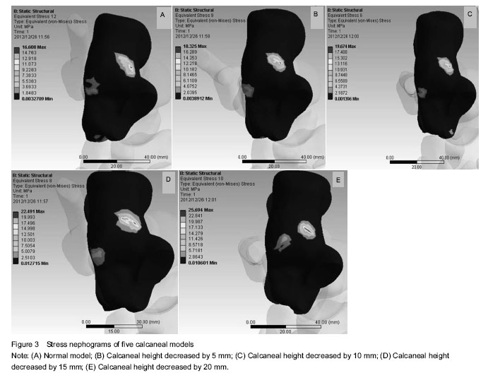
The stress distribution, the maximal stress and location of the five calcaneal models were evaluated.
Main outcome measures
Impact of changing degrees of the calcaneal height on the peak stress and the distribution.
.jpg)