Chinese Journal of Tissue Engineering Research ›› 2014, Vol. 18 ›› Issue (11): 1765-1773.doi: 10.3969/j.issn.2095-4344.2014.11.021
Previous Articles Next Articles
Effect of numerical simulation of vascular wall thickness on fluid-structure interaction analysis of complex intracranial aneurysms
Liu Bo, Li Zhi-wei
- Department of Neurology, Yongchuan Hospital, Chongqing Medical University, Chongqing 402160, China
-
Revised:2014-02-06Online:2014-03-12Published:2014-03-12 -
Contact:Li Zhi-wei, Chief physician, Professor, Department of Neurology, Yongchuan Hospital, Chongqing Medical University, Chongqing 402160, China -
About author:Liu Bo, Studying for doctorate, Attending physician, Department of Neurology, Yongchuan Hospital, Chongqing Medical University, Chongqing 402160, China -
Supported by:Natural Science Foundation of Yongchuan District of Chongqing City, No. Ycstc,2013nc8031
CLC Number:
Cite this article
Liu Bo, Li Zhi-wei . Effect of numerical simulation of vascular wall thickness on fluid-structure interaction analysis of complex intracranial aneurysms[J]. Chinese Journal of Tissue Engineering Research, 2014, 18(11): 1765-1773.
share this article
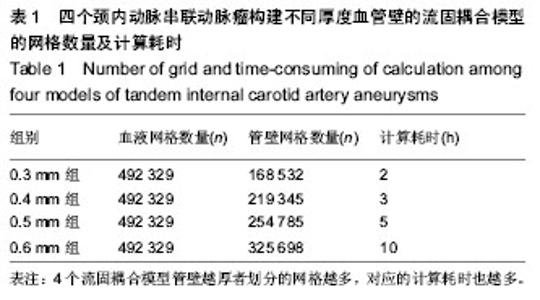
2.1 颈内动脉串联动脉瘤构建不同厚度血管壁的流固耦合模型的网格数量和计算耗时 由于4个流固耦合模型具有相同的血液模型,故划分的血液网格数量均为492 329个。而4个模型管壁存在差异,管壁越厚者划分的网格越多,从0.3 mm组至0.6 mm组分别是168 532个、219 345个、254 785个、325 698个,对应的计算耗时也逐渐增多,依次是2,3,5,10 h(表1)。"

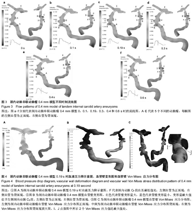
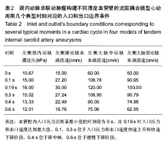
2.2 颈内动脉串联动脉瘤构建不同厚度血管壁的流固耦合模型的计算结果总体情况 观察4个模型流固耦合分析得到的血液流线图、血液压力降图、血管内壁壁面切应力图、血管壁变形情况分布图、血管壁Von Mises 应力分布图(图3-5)发现:在心动周期每个时刻血液流线图、血液压力降图、血管内壁壁面切应力图、血管壁变形情况分布图和血管壁Von Mises 应力分布图的ANSYS染色均无明显变化,只是色彩代表的值随时在变。上述几种分布图中4个模型之间ANSYS染色差别也不大,只是色彩代表的值存在差异。 2.3 颈内动脉串联动脉瘤构建不同厚度血管壁的流固耦合模型的血液流动情况 为了便于分析,如图3所示,选取心动周期几个典型时刻血管腔内流线图进行观察,取入口压力达到某最小值的时刻设为0 s,观察0,0.1,0.19,0.3,0.4,0.6 s血液流动情况,这几个时刻的左侧颈内动脉C2段压力、左侧眼动脉、左侧大脑中动脉、左侧大脑前动脉血流速度的对应值如表2。其中在0 s时入口压力和出口速度达到最小值,在0.19 s时入口压力和出口速度达到最大值。0.1,0.3 s位于入口压力和出口速度快速上升和快速下降阶段,0.4 s位于降中峡,0.6 s位于缓慢下降阶段。 观察0.4 mm模型心动周期不同时刻流线图发现,各时刻流线图的流速不停地在变化,在0.19 s时整个模型流速达到最大值,但每个时刻血液流动的总体样式基本一致,即在动脉瘤A,B,C,D,E血管腔内均形成明显漩涡,每个动脉瘤的漩涡类型在整个心动周期基本不变。整个心动周期在颈内动脉C7段流速均达到最大值,分别是 0 s(114.1 cm/s),0.1 s(213.2 cm/s),0.19 s(236.1 cm/s),0.3 s(214.2 cm/s),0.4 s(175.9 cm/s),0.6 s(146.0 cm/s)。整个心动周期血流速度在动脉瘤A,B,C,D瘤腔边缘均较低,在几个典型时刻瘤腔内血流速度最低值分别达到:0 s(0.2 cm/s),0.1 s(0.8 cm/s),0.19 s(0.9 cm/s),0.3 s (0.8 cm/s),0.4 s(0.2 cm/s),0.6 s(0.2 cm/s)。动脉瘤E瘤腔内流线呈螺旋状,部分区域流速快,部分较慢,且其速度分布在心动周期各时刻存在差异。 0.3,0.4,0.5,0.6 mm模型心动周期不同时刻流线图均有相同表现。由于每个模型计算了10个周期,每个周期0.19 s时C7段均是流速最大值,对10个周期流速最大值取均值,单因素方差分析结果显示4个模型差别无显著性意义(P > 0.05,表3)。"
"


"

"
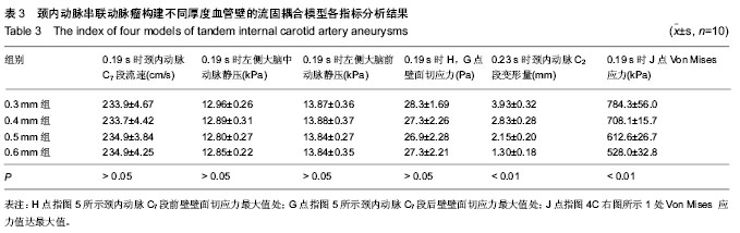
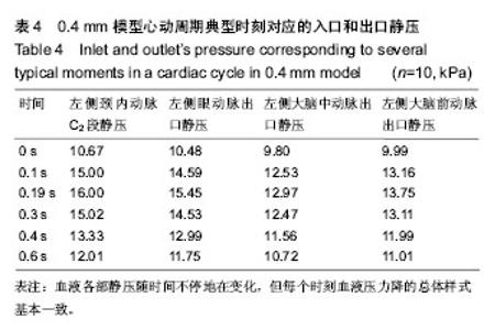
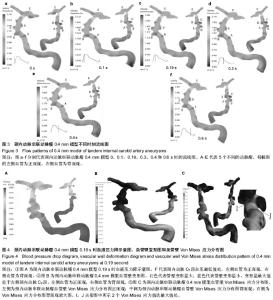
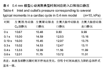
2.4 颈内动脉串联动脉瘤构建不同厚度血管壁的流固耦合模型的血流压力降分布情况 观察每个模型在心动周期不同时刻血液压力降分布情况发现,血液各部静压随时间不停地在变化,但每个时刻血液压力降的总体样式基本一致,如图4A所示,每个时刻血液压力降分布情况CFX-post染色得到的图像基本一样,但不同时刻其色彩代表的值不一样。观察整个流体域发现,压力由近及远逐渐下降,但在F点附近压力达到最低值,之后在E动脉瘤瘤腔内压力短暂上升,再缓慢下降。其中左侧眼动脉出口静压高于左侧大脑中动脉和左侧大脑前动脉,左侧大脑前动脉出口静压略高于左侧大脑中动脉。以0.4 mm模型为例,在心动周期几个典型时刻3个出口静压的具体值见表4。 由于每个模型计算了10个周期,每个周期0.19 s时左侧大脑中动脉、大脑前动脉出口静压均是最大值,对10个周期2个出口的静压最大值分别取均值,比较4个模型均值之间差异,经过单因素方差分析提示差别无显著性意义 (P > 0.05,表3)。"

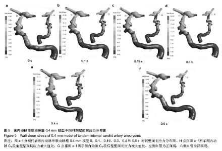
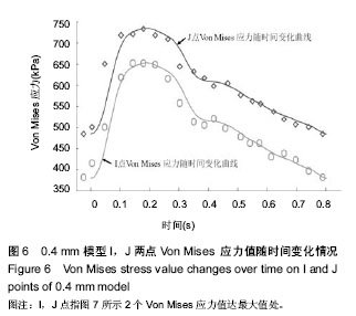
2.5 颈内动脉串联动脉瘤构建不同厚度血管壁的流固耦合模型的壁面切应力分布 如图5所示,该图是颈内动脉串联动脉瘤0.4 mm模型不同时刻壁面切应力分布图。动脉瘤A,B,C,D,E瘤腔内壁面切应力均不高,但在颈内动脉C7段靠近E动脉瘤处存在G和H点,此处壁面切应力在整个心动周期均明显高于其他区域,G和H点值大小相当。G和H点在心动周期各时刻壁面切应力的值是:0 s(8.28 Pa),0.1 s(3.89 Pa),0.19 s(28.57 Pa),0.3 s(24.00 Pa),0.4 s (17.11 Pa),0.6 s(12.61 Pa)。 在每个心动周期0.19 s时G,H点壁面切应力达最大值。由于每个模型计算了10个周期,每个周期0.19 s时G,H点均是最大值,计算10个周期G,H点最大值的均值,单因素方差分析显示4个模型的差异无显著性意义(P > 0.05,表3)。 2.6 颈内动脉串联动脉瘤构建不同厚度血管壁的流固耦合模型的血管壁变形情况 观察每个模型整个心动周期管壁变形图,发现每个时刻管壁变形图ANSYS渲染的色彩基本一致,说明整个模型管壁变形的区域分布情况固定不变。但由于整个心动周期模型内的血流速度和压力不停地在变化,故每个血管段的管壁变形量也在不停地变化。以0.4 mm模型为例,其中0.23 s时刻管壁变形量最大,如图4B所示,该图显示0.23 s时的管壁变形情况,变形最明显的是左侧颈内动脉C2段,颈内动脉颅内段变形较小。颈内动脉C2段管壁变形量最大可达2.78 mm,约占血管直径的30%,如果该段血管不在颅骨内走行,管壁移位震动将会很大。 由于每个模型计算了10个周期,每个周期均在0.23 s时C2段变形量最大,计算10个周期C2段变形量最大值的均值,比较4个模型均值之间差异,经过单因素方差分析提示差异有显著性意义(P < 0.01,表3),变形量大小排序依次是:0.3 mm模型(3.93 mm)>0.4 mm模型(2.83 mm) > 0.5 mm模型(2.15 mm)>0.6 mm模型(1.30 mm)。 2.7 颈内动脉串联动脉瘤构建不同厚度血管壁的流固耦合模型的血管壁内壁面Von Mises 应力分布 观察每个模型不同时刻内壁面Von Mises 应力分布图,发现不同时刻的Von Mises 应力的分布特性是一致的,即每个时刻ANSYS渲染的图形和图4C一样。如图4C所示,在A,B,C,D,E动脉瘤的根部附近出现Von Mises 应力增大,其中在I,J两点处达到局部最大值,I和J两点的值相差不大,J点略大于I点。由于血流速度和压力随时在变,血管壁内壁面同一点在不同时刻Von Mises 应力大小是不同的,其中在0.19 s时刻整个模型Von Mises 应力值达到最大值。观察 0.4 mm模型整个心动周期,绘制I,J两点Von Mises 应力值随时间变化曲线如图6。发现I,J两点Von Mises 应力值随时间变化的节奏和入口压力变化节奏一致,该曲线和左侧颈内动脉C2段灌注压曲线总体形态类似,即在整个心动周期里,Von Mises 应力值先快速升高,后减慢上升,在0.19 s时达到最大,之后快速下降,0.4 s后缓慢下降直至最低值。 4个模型Von Mises应力分布图类似,由于每个模型计算了10个周期,每个周期均在0.19 s时I,J两点Von Mises 应力达最大值,J点均略大于I点,计算10个周期J点Von Mises 应力达最大值的均值,比较4个模型均值之间差异,经过单因素方差分析提示差异有显著性意义(P < 0.01),见表3,大小排序依次是:0.3 mm模型(784.3 kPa) >0.4 mm模型(708.1 kPa)>0.5 mm模型(612.6 kPa)>0.6 mm模型(528.0 kPa)。"
| [1] 史跃,黄玉杰,蔡廷江,等.Willis环周围窄颈动脉瘤与栓塞材料选择的相关性[J].中国组织工程研究, 2012,16(3):547-550. [2] Huang YM, Chou IC, Jiang CP, et al. Finite element analysis of dental implant neck effects on primary stability and osseointegration in a type IV bone mandible. Biomed Mater Eng. 2014;24(1):1407-1415. [3] Lu S, Li T, Zhang Y, et al. Biomechanical optimization of the diameter of distraction screw in distraction implant by three-dimensional finite element analysis. Comput Biol Med. 2013;43(11):1949-1954.[4] Cift H, Deniz S, Ek?io?lu F. Determination of the effect on the proximal femoral load distribution of diaphyseal cement support in femoral intertrochanteric fractures with calcar defect by finite element analysis. Eklem Hastalik Cerrahisi. 2013;24(3):163-168. [5] von Sachsen S, Senf B, Burgert O, et al. Stent graft visualization and planning tool for endovascular surgery using finite element analysis. Int J Comput Assist Radiol Surg. 2013, in press.[6] Weichert F, Walczak L, Fisseler D, et al. Simulation of intra-aneurysmal blood flow by different numerical methods. Comput Math Methods Med. 2013;2013:527654. [7] Gambaruto AM, Janela J, Moura A, et al. Sensitivity of hemodynamics in a patient specific cerebral aneurysm to vascular geometry and blood rheology. Math Biosci Eng. 2011;8(2):409-423.[8] Chang HS. Simulation of the natural history of cerebral aneurysms based on data from the International Study of Unruptured Intracranial Aneurysms. J Neurosurg. 2006; 104(2):188-194.[9] Ohshima T, Miyachi S, Hattori K, et al. Risk of aneurysmal rupture: the importance of neck orifice positioning-assessment using computational flow simulation. Neurosurgery. 2008;62(4):767-775. [10] Ma B, Lu J, Harbaugh RE, et al. Nonlinear anisotropic stress analysis of anatomically realistic cerebral aneurysms. J Biomech Eng. 2007;129(1):88-96.[11] Torii R, Oshima M, Kobayashi T, et al. Fluid-structure interaction modeling of aneurysmal conditions with high and normal blood pressures. Comput Mech. 2006;38(4): 482-490. [12] 曾堃.不同截面支架治疗囊状和梭形动脉瘤的流固耦合数值模拟研究[D].北京:北京工业大学,2012. [13] 王芙昱,许百男,孙正辉,等.基于CTA影像数据的个体化颅内动脉瘤的流固耦合力学模型[J].南方医科大学学报, 2012,32(10): 1407-1414.[14] Sende J, Jabre P, Leroux B, et al. Invasive arterial blood pressure monitoring in an out-of-hospital setting: an observational study. Emerg Med J. 2009;26(3):210-212. [15] Hager H, Mandadi G, Pulley D, et al. A comparison of noninvasive blood pressure measurement on the wrist with invasive arterial blood pressure monitoring in patients undergoing bariatric surgery. Obes Surg. 2009;19(6): 717-724. [16] Cao H, Norris P, Ozdas A, et al. A simple non-physiological artifact filter for invasive arterial blood pressure monitoring: a study of 1852 trauma ICU patients. Conf Proc IEEE Eng Med Biol Soc. 2006;1:1417-1420.[17] Cebral JR, Löhner R. From medical images to anatomically accurate finite element grids. Inter J Numer Method Eng. 2001;51(8):985-1008. [18] Pedley TJ. The Fluid Mechanics of Large Blood Vessels. Cambridge, UK: Cambridge University Press. 1980.[19] Qiao A, Liu Y. Influence of graft-host diameter ratio on the hemodynamics of CABG. Biomed Mater Eng. 2006;16(3): 189-201.[20] Aenis M, Stancampiano AP, Wakhloo AK, et al. Modeling of flow in a straight stented and nonstented side wall aneurysm model. J Biomech Eng. 1997;119(2):206-212.[21] 付文宇,乔爱科.基于个性化颈内动脉瘤模型的流固耦合分析[J].医用生物力学,2012,27(4):421-426. [22] 闫亭亭,刘芳芳,陈雪,等.三角形截面丝裸支架治疗梭形颅内动脉瘤的流固耦合数值模拟研究[J].生物医学工程学杂志,2012, 29(5):867-871. [23] Di Martino ES, Guadagni G, Fumero A, et al. Fluid-structure interaction within realistic three-dimensional models of the aneurysmatic aorta as a guidance to assess the risk of rupture of the aneurysm. Med Eng Phys. 2001;23(9):647-655.[24] Wani A, Behari S, Lyndoh B, et al. Multiple aneurysms associated with agenesis of internal carotid artery. Turk Neurosurg. 2011;21(1):83-85.[25] Kaminogo M, Yonekura M, Shibata S. Incidence and outcome of multiple intracranial aneurysms in a defined population. Stroke. 2003;34(1):16-21. [26] Matouk CC, Mandell DM, Günel M, et al. Vessel wall magnetic resonance imaging identifies the site of rupture in patients with multiple intracranial aneurysms: proof of principle. Neurosurgery. 2013;72(3):492-496.[27] Li M, Lin N, Wu J, et al. Multiple intracranial aneurysms associated with multiple dural arteriovenous fistulas and cerebral arteriovenous malformation. World Neurosurg. 2012;77(2):398.E11-15. [28] Auricchio F, Conti M, Ferrara A, et al. Patient-specific finite element analysis of carotid artery stenting: a focus on vessel modeling. Int j numer method biomed eng. 2013;29(6):645- 664.[29] Bahraseman HG, Hassani K, Khosravi A, et al. Estimation of maximum intraventricular pressure: a three-dimensional fluid-structure interaction model. Biomed Eng Online. 2013; 12:122. [30] Le TB, Sotiropoulos F. Fluid-structure interaction of an aortic heart valve prosthesis driven by an animated anatomic left ventricle. J Comput Phys. 2013;244:41-62.[31] Morris PP, Choi IS. Cerebral vascular anatomy. Neuroimaging Clin N Am. 1996;6(3):541-560.[32] Liu B, Wang X, Zhu H, et al. ANSYS simulation of subcutaneous pustule electrical characteristics. Sheng Wu Yi Xue Gong Cheng Xue Za Zhi. 2011;28(6):1110-1113.[33] Hu Z, Lu P, Xie H, et al. The study of noninvasive ventilator impeller based on ANSYS. Sheng Wu Yi Xue Gong Cheng Xue Za Zhi. 2011;28(3):456-459.[34] Peng D, Yu F, Hu J, et al. Boundary conditions for simulating large SAW devices using ANSYS. IEEE Trans Ultrason Ferroelectr Freq Control. 2010;57(8):1712-1714. [35] Qi R, Ng D, Cormier BR, et al. Numerical simulations of LNG vapor dispersion in Brayton Fire Training Field tests with ANSYS CFX. J Hazard Mater. 2010;183(1-3):51-61.[36] Salvi D, Boldor D, Ortego J, et al. Numerical modeling of continuous flow microwave heating: a critical comparison of COMSOL and ANSYS. J Microw Power Electromagn Energy. 2010;44(4):187-197.[37] 郭星辉,崔海坡,徐秀林.平衡功能障碍康复训练装置的有限元分析[J].中国组织工程研究,2012,16(26):4863-4866. [38] 陈纪宝,奚春阳,焦力刚,等.有限元分析在腰椎生物力学应用中的研究与进展[J].中国组织工程研究,2012,16(26):4908-4912. [39] 黄宇文.有限元分析在口腔生物力学中的应用[J].中国组织工程研究,2012,16(13):2423-2426. [40] 吴克启,舒朝晖.高等流体力学[M].北京:中国电力出版社,2009.[41] 伍悦滨.高等流体力学[M].哈尔滨:哈尔滨工业大学出版社,2013.[42] 王松岭.高等工程流体力学[M].北京:中国电力出版社,2011.[43] Hynecek RL, Sadek M, Derubertis BG, et al. Evaluation of pressure transmission and intra-aneurysmal contents after endovascular repair using the Trivascular Enovus expanded polytetrafluoroethylene stent graft in a canine model of abdominal aortic aneurysm. J Vasc Surg. 2007;46(5):1005- 1013. [44] Timaran CH, Ohki T, Veith FJ, et al. Influence of type II endoleak volume on aneurysm wall pressure and distribution in an experimental model. J Vasc Surg. 2005;41(4):657-663.[45] Takeuchi S, Karino T. Flow patterns and distributions of fluid velocity and wall shear stress in the human internal carotid and middle cerebral arteries. World Neurosurg. 2010 Mar; 73(3):174-85; discussion e27. [46] Yosibash Z, Tal D, Trabelsi N. Predicting the yield of the proximal femur using high-order finite-element analysis with inhomogeneous orthotropic material properties. Philos Trans A Math Phys Eng Sci. 2010;368(1920):2707-2723. [47] Schwiedrzik JJ, Wolfram U, Zysset PK. A generalized anisotropic quadric yield criterion and its application to bone tissue at multiple length scales. Biomech Model Mechanobiol. 2013;12(6):1155-1168. [48] Wang F, Xu B, Sun Z, et al. [Individualized fluid-solid coupled model of intracranial aneurysms based on computed tomography angiography data]. Nan Fang Yi Ke Da Xue Xue Bao. 2012;32(10):1407-1414. [49] Bai-Nan X, Fu-Yu W, Lei L, et al. Hemodynamics model of fluid-solid interaction in internal carotid artery aneurysms. Neurosurg Rev. 2011;34(1):39-47. [50] Mieth A, Revermann M, Babelova A, et al. L-type calcium channel inhibitor diltiazem prevents aneurysm formation by blood pressure-independent anti-inflammatory effects. Hypertension. 2013;62(6):1098-1104. [51] Gaál EI, Salo P, Kristiansson K, et al. Intracranial aneurysm risk locus 5q23.2 is associated with elevated systolic blood pressure. PLoS Genet. 2012;8(3):e1002563. |
| [1] | Xie Qiang. Three-dimensional finite element model for biomechanical analysis of stress in knee inversion and external rotation after posterior cruciate ligament rupture [J]. Chinese Journal of Tissue Engineering Research, 2017, 21(7): 1036-1040. |
| [2] | He Ze-dong, Zhao Jing, Chen Liang-yu, Li Ke, Weng Jie. Multilevel finite element analysis on the biological tribology damage of water on bone tissue [J]. Chinese Journal of Tissue Engineering Research, 2017, 21(7): 1041-1045. |
| [3] | Li Hui, Ma Jun-yi, Ma Yuan, Zhu Xu . Establishment of a three-dimensional finite element model of ankylosing spondylitis kyphosis [J]. Chinese Journal of Tissue Engineering Research, 2017, 21(7): 1069-1073. |
| [4] | Du Shi-yao, Zhou Feng-jin, Ni Bin, Chen Bo, Chen Jin-shui. Finite-element analysis of a novel posterior atlantoaxial restricted non-fusion fixation system [J]. Chinese Journal of Tissue Engineering Research, 2017, 21(3): 383-389. |
| [5] | Zhang Li-chao, Zhang Li-min, Lv Yong-ming, Wang Zhi-hui, Yang Yang, Xu Fei, Dai Hai-feng, Li Jia, Cao Xiang-yu, Wu Li-zhu. Finite element analysis of knee flexion and extension movement [J]. Chinese Journal of Tissue Engineering Research, 2017, 21(3): 396-400. |
| [6] | Jia Jin-ling, Dong Yu-zhen. Finite element analysis of prosthesis position during hip arthroplasty [J]. Chinese Journal of Tissue Engineering Research, 2017, 21(3): 401-405. |
| [7] | Ma Yong, Sikandaer•Siyiti, Ou Yong, Aikeremujiang•Muheremu, Ma Yuan. Finite element analysis of kyphosis in ankylosing spondylitis treated by different osteotomy methods [J]. Chinese Journal of Tissue Engineering Research, 2017, 21(19): 3038-3043. |
| [8] | Wang Chun-cheng, Li Ming-zhe. Position and biomechanical characteristics of prosthesis in total hip arthroplasty [J]. Chinese Journal of Tissue Engineering Research, 2017, 21(11): 1652-1657. |
| [9] | Xiong Sheng, Chen Xi-liang, Wang Yun-feng, Hu Yong. Optimization design and simulation analysis of artificial atlanto-odontoid joint structure [J]. Chinese Journal of Tissue Engineering Research, 2016, 20(48): 7169-7174. |
| [10] | Hu Qun-sheng, Jiang Zi-wei, Huang Feng. Finite element analysis of unstable intertrochanteric fracture fixed with triangle proximal femoral nail [J]. Chinese Journal of Tissue Engineering Research, 2016, 20(48): 7219-7224. |
| [11] | Song Zuo-cheng, Yan Xiao-long. Biomechanical characteristics of distal tibial articular surface defect of the ankle joint: three-dimensional finite element analysis [J]. Chinese Journal of Tissue Engineering Research, 2016, 20(48): 7212-7218. |
| [12] | Liu Ya-pu, Hou Xiu-wei, Wu Guang-liang, Xia Hong. Comparison of stress distribution of adjacent segments after artificial cervical disc replacement versus anterior cervical discectomy and fusion: a finite element analysis [J]. Chinese Journal of Tissue Engineering Research, 2016, 20(44): 6541-6548. |
| [13] | Jiang Zi-wei, Huang Feng, Zheng Xiao-hui, Hu Qun-sheng, Pang Zhi-hui, Zhou Guang-quan, Li Yue . Different fixations for intertrochanteric fracture affect proximal femur stress: a finite element analysis [J]. Chinese Journal of Tissue Engineering Research, 2016, 20(44): 6599-6605. |
| [14] | Li Peng-fei, Du Gen-fa, Lin Zi-ling, Pang Zhi-hui, Fan Yue-guang, He Xiang-xin, Sun Wen-tao,Chen Jin-lun. Finite element analysis of elderly femoral neck fracture based on LS-DYNA [J]. Chinese Journal of Tissue Engineering Research, 2016, 20(44): 6606-6611. |
| [15] | Li Zhong-hai, Lin Bin, Tang Jia-guang, Ren Dong-feng, Li Li, Wu Wen-wen, Hou Shu-xun. Biomechanics characteristics of four anterior cervical reconstructive techniques in the surgical management of multilevel cervical spondylotic myelopathy: a finite element model study [J]. Chinese Journal of Tissue Engineering Research, 2016, 20(44): 6612-6619. |
| Viewed | ||||||
|
Full text |
|
|||||
|
Abstract |
|
|||||