中国组织工程研究 ›› 2022, Vol. 26 ›› Issue (36): 5770-5774.doi: 10.12307/2022.788

• 骨与关节生物力学 bone and joint biomechanics • 上一篇    下一篇

单枚下胫腓联合螺钉不同角度固定下胫腓损伤的生物力学特性

米  涛,丁军稳,李泽清,唐保明,任  荣,李钊伟   

  1. 青海大学附属医院,青海省西宁市   810000
  • 收稿日期:2021-10-08 接受日期:2021-11-27 出版日期:2022-12-28 发布日期:2022-04-26
  • 通讯作者: 李钊伟,教授,硕士生导师,青海大学附属医院,青海省西宁市 810000
  • 作者简介:米涛,男,1993年生,湖南省怀化市人,汉族,青海大学在读硕士,主要从事创伤骨科方面的研究。 丁军稳,男,1991年生,江苏省徐州市人,汉族,青海大学在读硕士,主要从事创伤骨科方面的研究。
  • 基金资助:
    青海省科技厅项目(2020-ZJ-773),项目负责人:李钊伟

Biomechanical properties of a single inferior tibiofibular screw with different angles for fixing inferior tibiofibular injury

Mi Tao, Ding Junwen, Li Zeqing, Tang Baoming, Ren Rong, Li Zhaowei   

  1. Affiliated Hospital of Qinghai University, Xining 810000, Qinghai Province, China
  • Received:2021-10-08 Accepted:2021-11-27 Online:2022-12-28 Published:2022-04-26
  • Contact: Li Zhaowei, Professor, Master’s supervisor, Affiliated Hospital of Qinghai University, Xining 810000, Qinghai Province, China
  • About author:Mi Tao, Master candidate, Affiliated Hospital of Qinghai University, Xining 810000, Qinghai Province, China Ding Junwen, Master candidate, Affiliated Hospital of Qinghai University, Xining 810000, Qinghai Province, China Mi Tao and Ding Junwen contributed equally to this article.
  • Supported by:
    Qinghai Science and Technology Department Project, No. 2020-ZJ-773 (to LZW)

摘要:

文题释义:
下胫腓联合螺钉固定:下胫腓损伤手术方式的金标准仍是推荐的一至两枚横行金属螺钉坚强内固定,但螺钉置入的位置及大小、数目、穿透皮质层数等均存在较多的争议,而在角度的选择上多根据AO建议向前20°-30°进行置入,而选择向上的角度置入少有报道。
有限元分析:将CT扫描得到的图像数据导入计算机有限元软件中,利用有限元软件确定研究对象的求解域,并将求解域划分为有限大小和形状且彼此相连、相互作用的有限个单元,对每一单元假定一个较简单的近似解,然后推导求解这个域总的满足条件,从而得到问题的解。

背景:下胫腓联合损伤后的螺钉置入存在较多的争议,且随着计算机技术的逐渐发展,有限元法被不断应用在骨科领域中,该技术的可靠性也得到了显著提升。
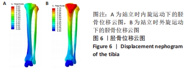
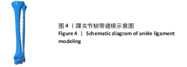
目的:通过建立踝关节三维有限元模型,研究单枚下胫腓联合螺钉不同角度置入固定下胫腓时的生物力学特性。
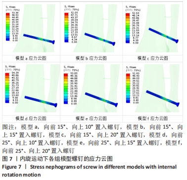
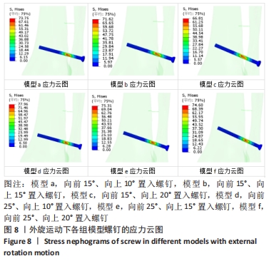
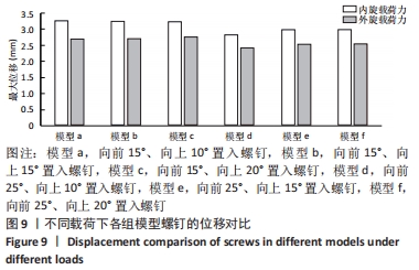
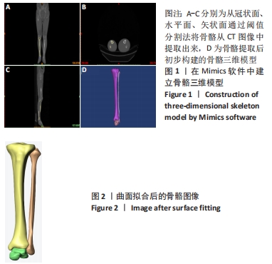
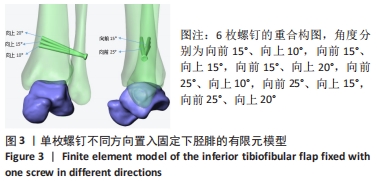
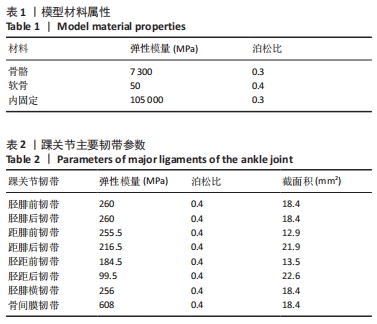
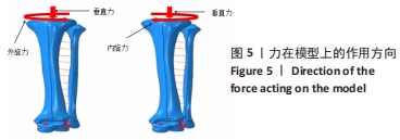
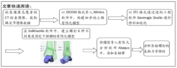
方法:基于健康志愿者断层CT图像基础,利用Mimics软件、Geomagic Studio软件建立踝关节模型并进行有效性验证,将模型导入Solidworks软件中,通过建立螺钉6种不同角度(模型a:向前15°、向上10°,模型b:向前15°、向上15°,模型c:向前15°、向上20°,模型d:向前25°、向上10°,模型e:向前25°、向上15°,模型f:向前25°、向上20°)置入固定下胫腓的有限元模型,模拟人体中立位单足站立时踝关节的受力方式,比较不同角度置入固定方式下螺钉的最大应力分布及螺钉的最大位移。
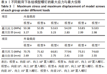
结果与结论:①在内旋、外旋载荷下,螺钉的最大应力点均在胫腓骨之间靠近胫骨处,在内旋载荷下,模型a、b、c、d、e、f的最大应力分别为53.38,52.05,52.63,54.39,53.85,52.83 MPa;在外旋载荷下,模型a、b、c、d、e、f螺钉的最大应力分别为73.75,71.62,66.81,77.96,75.31,74.60 MPa;②在内旋载荷下,模型a、b、c、d、e、f的最大位移分别为3.27,3.25,3.2,2.83,2.99,2.98 mm;在外旋载荷下,模型a、b、c、d、e、f螺钉的最大位移分别为2.69,2.71,2.75,2.41,2.53,2.55 mm;③结果提示,在内旋、外旋载荷下,螺钉在向前25°置入固定时得到了更强的踝关节稳定性。 

https://orcid.org/0000-0002-4752-4405 (米涛)

中国组织工程研究杂志出版内容重点:人工关节;骨植入物;脊柱;骨折;内固定;数字化骨科;组织工程

关键词: 下胫腓, 螺钉, 生物力学, 有限元分析, 角度

Abstract: BACKGROUND: There are still many controversies about how to implant the tibiofibular joint screw. With the gradual development of computer technology, finite element method has been continuously applied in the field of orthopedics, and the reliability of this technology has been greatly improved.
OBJECTIVE: To study the biomechanical characteristics of different angle fixation of the tibiofibular syndesmosis with a single tibiofibular syndesmosis screw by establishing a three-dimensional finite element model of the ankle joint. 
METHODS: Based on the CT image, Mimics software and Geomagic Studio software were used to establish the ankle joint model and verify its validity. The model was imported into Solidworks software. The finite element model of fixing the inferior tibiofibular joints with screws at six different angles (Model a: 15° forward, 10° upward, model b: 15° forward, 15° upward, model c: 15° forward, 20° upward, model d: 25° forward, 10° upward, model e : 25° forward, 15° upward, model f: 25° forward, 20° upward) was established to simulate the force mode of the ankle joint when the human body stood on one foot in neutral position. The maximum stress distribution and the maximum displacement of screws with different angle fixing methods were compared.
RESULTS AND CONCLUSION: (1) Under internal rotation and external rotation loads, the maximum stress point of the screw was between the tibia and fibula near the tibia. Under internal rotation load, the maximum stresses of models a, b, c, d, e, and f were 53.38, 52.05, 52.63, 54.39, 53.85, and 52.83 MPa, respectively. Under external rotation load, the maximum stresses of models a, b, c, d, e, and f screw were 73.75, 71.62, 66.81, 77.96, 75.31, and 74.60 MPa, respectively. (2) Under internal rotation load, the maximum displacements of models a, b, c, d, e, and f were 3.27, 3.25, 3.2, 2.83, 2.99, and 2.98 mm, respectively. Under external rotation load, the maximum displacements of models a, b, c, d, e, and f screw were 2.69, 2.71, 2.75, 2.41, 2.53, and 2.55 mm. (3) In conclusion, under internal and external rotation loads, the screw position is fixed at an angle of 25° forward for greater stability.

Key words: inferior tibiofibular, screw, biomechanics, finite element analysis, angle

中图分类号: